
Environmental and EMC Qualification for Commercial and Military Aircraft Systems and Avionics.
Aircraft manufacturers, avionics suppliers, and aerospace equipment developers face a unique challenge: demonstrating that equipment can operate safely and reliably within the aircraft environment without adversely affecting other onboard systems.
RTCA DO-160 serves as the industry's primary environmental and electromagnetic compatibility standard for airborne equipment, providing test procedures used to support FAA certification programs, aircraft OEM requirements, and military aviation applications.
Intertek helps manufacturers navigate RTCA DO-160 qualification requirements by identifying applicable test categories, developing qualification strategies, and executing environmental, electrical, EMC, and lightning evaluations required for airborne equipment approval.
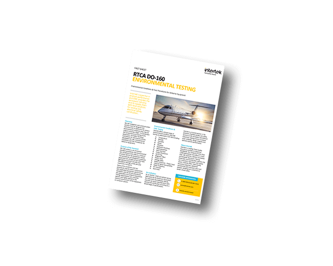
Learn more information on Intertek's testing and performance solutions for RTCA DO-160: Environmental Conditions & Test Procedures for Airborne Equipment with our complimentary fact sheet download.
Understanding RTCA DO-160 Compliance Requirements
RTCA DO-160, Environmental Conditions and Test Procedures for Airborne Equipment, establishes environmental and electromagnetic compatibility test procedures for equipment installed on aircraft.
Unlike a single pass/fail certification program, RTCA DO-160 consists of multiple test sections that are selected based on:
- Equipment installation location
- Aircraft type
- Operating environment
- Electrical characteristics
- Intended function
- Aircraft OEM requirements
- FAA certification objectives
Successful qualification typically includes:
- Determination of applicable DO-160 sections
- Development of a qualification test plan
- Execution of required environmental and EMC testing
- Documentation of results
- Qualification reporting
Because equipment installed in the cockpit experiences different conditions than equipment installed in an engine compartment or external aircraft location, the applicable test categories often vary significantly.
DO-160 Test Sections
Verifies equipment performance across a wide thermal range combined with low-pressure altitude simulation. Tests cover ground survival temperatures, short-term and long-term operating temperature extremes, in-flight loss-of-cooling scenarios, decompression from pressurized to unpressurized conditions, and overpressure exposure. Equipment categories span from pressurized cockpit locations (A1) through unpressurized external mounting (D3), with temperature ranges from -55°C to +85°C and altitudes up to 70,000 feet (21,300 m). This is the most installation-specific section of DO-160, requiring careful category selection based on aircraft type and mounting location.
Assesses an equipment assembly's ability to withstand rapid transitions between temperature extremes. Test ramps range from 2°C/min to 10°C/min depending on the selected category, spanning temperatures from -55°C to +85°C over multiple cycles. The primary concern is thermal fatigue: differential expansion between dissimilar materials, solder joint cracking, connector seal degradation, and delamination of printed circuit boards. Equipment must maintain functional performance during and after thermal cycling without physical damage.
Evaluates resistance to high-moisture environments that can cause corrosion, conductor degradation, insulation breakdown, and chemical changes in materials. The standard test profile runs 10 consecutive 24-hour cycles at temperatures cycling between 30°C and 65°C with relative humidity up to 95% RH. Equipment must operate as specified and show no harmful physical degradation following exposure. Humidity testing is particularly important for equipment installed in cargo bays, wheel wells, and other locations subject to condensation or rainwater ingress.
Subjects equipment to mechanical shock pulses representative of hard landings, runway events, in-flight turbulence encounters, and crash load cases. Operational shock tests use half-sine or trapezoidal pulses specified by peak acceleration (g) and duration. Crash safety testing applies sustained loads in multiple axes to ensure equipment remains attached to its mount under emergency deceleration conditions, reducing the risk of secondary injury to occupants or damage to adjacent systems. Test severity is aircraft-type dependent, with helicopter installations facing the most demanding profiles.
Demonstrates that airborne equipment meets performance and structural durability requirements across installation-specific vibration environments. Three test types address different scenarios: the Standard Vibration Test (Category S) uses broadband random profiles for fixed-wing aircraft; the Robust Vibration Test (Categories R, U, U2) targets equipment installed near engines, propellers, or in high-vibration zones; and the High-Level Short-Duration Test (Categories H, Z) simulates severe but brief vibration events. Profiles vary by aircraft type (jet, turboprop, piston, helicopter), installation zone, and mounting configuration. This section is one of the most commonly required for avionics qualification.
Determines whether equipment can be safely operated in a potentially explosive atmosphere, such as fuel vapors present in wheel wells, fuel tank bays, or areas adjacent to fuel systems. Test articles are placed in a closed chamber filled with a combustible gas mixture at specified concentrations, then energized through normal operating cycles. The test passes only if no ignition of the surrounding atmosphere occurs. This section applies selectively based on installation location and is not required for most avionics rack or pressurized-cabin installations.
Establishes equipment resistance to water ingress under conditions representative of condensation, dripping, and spray scenarios encountered in aircraft operations. Four equipment categories address increasing levels of water exposure: Category W covers dripping condensation, Category R addresses dripping water, Category S applies to spray, and Category T covers externally mounted equipment subject to direct rainfall and washing. Equipment must continue to function within specification during and after water exposure, with no harmful accumulation of moisture in enclosures or degradation of seals.
Determines whether equipment construction materials can withstand contact with common aviation fluids without degradation. Test fluids include hydraulic fluids, fuels (Jet-A, aviation gasoline), lubricating oils, de-icing and anti-icing compounds, cleaning solvents, and fire extinguishing agents. Equipment is exposed to each applicable fluid by immersion, spray, or brush application, then tested for continued functional performance and inspected for physical damage. This section applies only when equipment will be installed in locations where fluid contamination is reasonably expected.
Tests resistance to blowing sand and fine dust particles carried by air movement at moderate velocities. Primary adverse effects include penetration into crevices and bearings causing fouling of moving parts, abrasion of optical surfaces and display screens, clogging of ventilation filters, and interference with connector mating. The test subjects equipment to an airborne concentration of specified particle sizes and flow velocities for a defined duration, after which the equipment must meet its performance specification. Applicable primarily to equipment in unpressurized zones or aircraft operated in desert or high-particulate environments.
Evaluates whether equipment materials support fungal growth that could degrade performance over time in warm, humid operating environments. Equipment using organic materials such as certain plastics, adhesives, or coatings must either use fungus-resistant formulations or demonstrate by exposure test that the materials do not support growth of a standard fungal spore mixture at 29°C and 95% RH over a 28-day period. Fungal growth can degrade insulation, create conductive pathways, obstruct optical elements, and cause structural weakening.
Assesses equipment durability when exposed to a saline fog environment simulating marine coastal and shipboard operating conditions. The test subjects equipment to a 5% sodium chloride solution atomized into a fog at 35°C for a specified duration, followed by a humidity exposure period. Salt fog accelerates corrosion of metallic surfaces, degrades protective coatings, and can cause galvanic corrosion at dissimilar metal interfaces. Equipment must pass visual inspection for corrosion and meet functional performance requirements after exposure. Primarily required for rotorcraft or aircraft operating in maritime environments.
Determines the magnetic field generated by equipment and ensures the equipment does not cause unacceptable deflection of aircraft compass systems. Electronic circuits carrying current produce magnetic fields, and ferromagnetic materials can distort the local Earth field. The test measures deflection of a compass positioned at a reference distance from the energized equipment and compares the result against category limits. The Earth's horizontal magnetic field at the test location is characterized to establish a deflection constant, enabling the lab measurement to be normalized to the standard reference field of 14.4 A/m.
The largest and most complex section of DO-160, covering both the susceptibility of equipment to power quality variations and the emissions the equipment generates back onto the aircraft power bus. Tests include normal operating voltage range, voltage transients, power interruptions and dropouts, frequency variations for AC systems (360-800 Hz), phase imbalance, and abnormal overvoltage or undervoltage conditions. The emissions side covers conducted current harmonics, power factor, and re-generated energy. Aircraft power buses covered include 28V DC, 115V AC single-phase and three-phase AC systems, as well as emerging high-voltage 270V DC and 540V DC architectures.
Verifies that equipment can withstand fast, high-voltage transient spikes induced on power input lines by other equipment switching on the aircraft bus. The test applies a series of damped sinusoidal or double-exponential spike waveforms of specified peak amplitude and rise time to the equipment power pins while the unit operates. Aircraft power systems are prone to spikes from motor-driven loads, relay switching, and generator transients. Equipment must continue to function within specification during and after spike exposure without latch-up, reset, or damage.
Determines whether equipment will accept audio-frequency interference components superimposed on its DC or AC power supply lines without degrading performance. The test sweeps sinusoidal interference at frequencies from 400 Hz to 150 kHz (or higher, depending on category) across the power input at specified voltage levels. This reflects the reality that aircraft power buses carry ripple and interference from generators, inverters, and other switching loads. Equipment must maintain function throughout the sweep. This section is distinct from Section 19, which addresses interference on signal lines rather than power lines.
Evaluates whether equipment interconnect wiring can tolerate low-frequency electromagnetic interference induced from nearby cables or the aircraft structure. Unlike Section 18 which focuses on power line conducted interference, Section 19 targets signal lines and determines whether induced currents or voltages on those lines cause equipment malfunction. Test methods inject calibrated interference signals at frequencies from DC to 400 Hz into equipment interconnect harnesses. Categories define the severity of exposure based on proximity to high-current wiring and the shielding effectiveness of the installation environment.
Tests whether equipment continues to operate correctly when exposed to radiated and conducted radio frequency fields representing the electromagnetic environment found on aircraft. The radiated test exposes equipment to RF fields from 100 MHz to 18 GHz (or higher for some categories), simulating emissions from aircraft communication and navigation transmitters, ground radar, and High-Intensity Radiated Fields (HIRF) from external radar systems. Testing may be conducted in a semi-anechoic chamber or a reverberation chamber. The conducted test applies RF signals directly to equipment interconnect cables. Categories range from Category B (routine commercial aviation) through Category R and W (HIRF-intense environments).
Measures unintentional radio frequency energy radiated and conducted from equipment onto its interconnect cables, ensuring emissions remain below limits that could interfere with aircraft communication and navigation receivers. Radiated emissions are measured from 100 MHz to 6 GHz using either a semi-anechoic chamber or reverberation chamber method. Conducted emissions on interconnect cables are measured from 150 kHz to 152 MHz. Transmitters in receive mode and non-keyed transmitters must also meet limits on spurious emissions. Category limits are set based on the sensitivity of aircraft receivers to interference and the proximity of wiring to those receivers.
Verifies that equipment can withstand transient voltages and currents induced in its wiring by a nearby lightning strike on the aircraft structure. Lightning current flowing through the airframe induces transient waveforms on attached wiring through inductive and capacitive coupling. The test uses pin injection methods to demonstrate damage tolerance and cable bundle injection to demonstrate upset tolerance. Multiple waveform types are specified, including single stroke, multiple stroke, and multiple burst profiles that replicate the complex temporal structure of actual lightning events. This section is among the most technically demanding in DO-160 and is closely related to the requirements of MIL-STD-464.
Addresses the threat of direct lightning attachment to equipment or its enclosure, as distinct from the induced transients of Section 22. Direct attachment can cause physical damage including burn-through, arc pitting, fastener blow-out, and composite skin delamination. The test subjects equipment or representative structural samples to the physical and thermal effects of lightning current components: Component A (initial return stroke), Component B (intermediate current), Component C (continuing current), and Component D (restrike). Applicable primarily to externally mounted equipment, antennas, and airframe structural elements at zone locations exposed to direct strike probability.
Determines performance characteristics for equipment that must operate in icing conditions resulting from rapid changes in temperature, altitude, and humidity. Three test procedures address different icing mechanisms: external ice and frost formation, ice caused by freezing of condensed water, and ice build-up from direct water exposure. Equipment is cycled through temperature and humidity profiles that cause moisture to condense and freeze on surfaces, and must then demonstrate continued functional operation within specification. Applicable to externally mounted equipment, pitot-static probes, ice detection systems, and any avionics exposed to the outside air environment.
Tests equipment resilience to electrostatic discharge events that occur when a person touches the equipment after accumulating a static charge. Contributing factors include low relative humidity, synthetic carpet or seat materials, and dry air circulation in pressurized cabins. The test applies ESD pulses of specified voltage (typically 2 kV to 15 kV depending on category) from a human body model to accessible external surfaces and connector pins, following methods closely aligned with IEC 61000-4-2. Equipment must not sustain permanent damage or exhibit unacceptable functional degradation during or after exposure. This section applies to any equipment accessible to flight crew or maintenance personnel.
Verifies that equipment materials and construction do not serve as an ignition source or propagate fire in the aircraft interior. Test methods and applicable categories differ based on installation location and aircraft type. For most interior installations, material flammability is evaluated against FAA-accepted methods derived from the FAA Fire Test Handbook, covering vertical Bunsen burner, horizontal burn, and radiant panel tests. Category A applies to equipment where flammability must be demonstrated; Category B covers equipment exempt from testing due to small size or installation in a fire-suppressed zone. Note that DO-160G Section 26 is accepted for FAR Part 25 aircraft but not for Part 33 engine certification, which requires separate compliance per AC 33.17-1.
Products Requiring RTCA DO-160 Testing
RTCA DO-160 testing is commonly performed on:
- Flight displays
- Cockpit electronics
- Communication systems
- Navigation equipment
- Flight control systems
- Aircraft sensors
- Power conversion equipment
- Aircraft lighting products
- Battery systems
- In-flight entertainment equipment
- Airborne networking devices
- Aerospace electronics
- UAV avionics
- Aerospace instrumentation
RTCA DO-160 - Frequently Asked Questions (FAQs)
No. RTCA DO-160 provides environmental and EMC test procedures for airborne equipment. Compliance is demonstrated through successful completion of applicable test sections and supporting qualification documentation.
Applicable sections are determined by the equipment's installation location, intended function, aircraft type, electrical characteristics, and certification requirements.
Temperature and altitude, vibration, EMC, lightning induced transients, power input, waterproofness, and fluids susceptibility evaluations are among the most commonly requested.
Yes. Intertek works with manufacturers to review product applications, installation environments, and certification objectives to help identify applicable DO-160 sections and qualification requirements.
Related Links

Performance Testing for Military & Aerospace (FATs, MIL-STD-810, RTCA DO-160)
From initial project stage and test plan origination to pre-compliance testing and final qualification report issuance